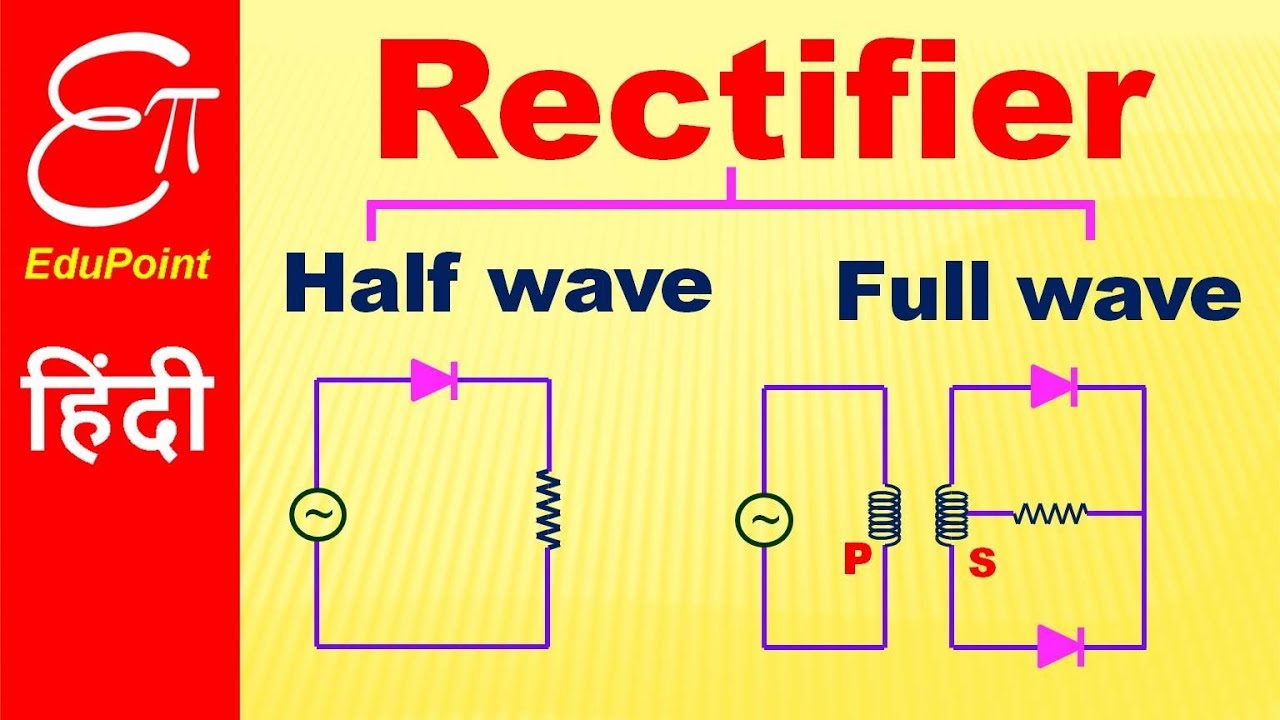
Half Wave Full Wave Rectifier Circuit Diagram Rectifier Wave
Rectifier half output voltage principle Half wave and full wave rectifier How the half wave rectifier circuit works wiring view and schematics
What Is Half Wave And Full Wave Rectifier Operation Amp Circuit Diagram
Half voltage full high wave rectifier electrical engineering rectifiers transformer circuits capacitor cycle conducting maximum secondary max Half wave rectifier basics circuit working amp applications อัลบั้ม 104+ ภาพ วงจร เรียง กระแส แบบ เต็ม คลื่น full wave rectifier
What is half wave and full wave rectifier operation amp circuit diagram
What is single phase full wave controlled rectifier? working, circuitCircuit of half wave rectifier low price, save 70% Rectifier circuit diagramHalf wave & full wave rectifier: working principle, circuit diagram.
With neat circuit diagram and waveforms explain the operation of fullWhat is half wave and full wave rectifier? Half wave rectifier basics, circuit, working applications, 50% offSingle phase half wave rectifier- circuit diagram,theory & applications.

Comparison of half wave rectifiers and full wave rectifiers
Rectifier wave half full circuit diagram diode rectification crystal operation connected used ac supply shown below throughHalf wave rectifier(explanation) Rectifier waveformRectifier rectifiers circuits.
High voltage facts for undergraduate and postgraduate students ofRectifier wave half Center tapped full wave rectifier circuit diagram.


What is Half Wave and Full Wave Rectifier? - Operation & Circuit

Half Wave Rectifier Basics Circuit Working Amp Applications - Riset
What Is Half Wave And Full Wave Rectifier Operation Amp Circuit Diagram

Center Tapped Full Wave Rectifier Circuit Diagram

Single Phase Half Wave Rectifier- Circuit Diagram,Theory & Applications

With Neat Circuit Diagram And Waveforms Explain The Operation Of Full

half wave and full wave rectifier | half wave vs full wave rectifiers

How The Half Wave Rectifier Circuit Works Wiring View And Schematics

Comparison of Half wave Rectifiers and Full wave Rectifiers

What is Single Phase Full Wave Controlled Rectifier? Working, Circuit