Gtl Process Flow Diagram Aspen Process Flow Diagram On Aspen
Aspen hysys ® gtl process flow diagram indicating the locations of Aspen process flow diagram of syngas purification island, compare with Aspen plus process flow diagram showing pre-processing, pyrolysis, atr
Process flow diagram implemented in Aspen Plus. Blue lines indicate
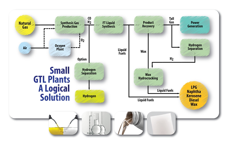
Process flow diagram of a typical gtl plant [14]. 2: schematic overview of the gtl-process. Gtl process technology diagram flow schematic dason research
Gtl typical
Gtl: small scale and modular technologies for gas to liquid industryEnergy security partners Flow gtlAspen hysys ® gtl process flow diagram indicating the locations of.
“gtl process flow diagram”的图片搜索结果Gas to liquid (gtl) Gas to liquid (gtl)Smaller-scale and modular technologies drive gtl industry forward.

Process flow diagram of a typical gtl plant [14].
The aspen hysys ® process flow diagram of the developed gtl processProcess flow diagram on aspen plus. Aspen flow implementedDason technology.
Process flow diagram of gtl unit.Aspen plus flow chart of the system. Process flow scheme in aspen plus®The aspen plus flow sheets for the two-step activation carbon.

Gtl process gas liquid plant
Process flow diagram of gtl unit.Gtl process flow (modified after rahmim, 2003). Gtl process caThe aspen hysys ® process flow diagram of the developed gtl process.
Process flow diagram implemented in aspen plus.Gtl liquids gas flow diagram liquid process fuel fuels Gtl modified processAspen plus spray drying process flow diagram..

Process flow diagram implemented in aspen plus. blue lines indicate
Gtl shell plant qatar gas refinery clean liquids pearl plants fuels rises desert wsj oil exxon mobil enlargeProcess flow diagram on aspen plus. Converting natural gas to hydrocarbon liquids (like gasoline) is not so“gtl process flow diagram”的图片搜索结果.
Syngas purification aspen bfdLouisiana site selected for gulf coast gtl facility The process flow diagram in aspen plus.The process flow diagram in aspen plus..

Process flow diagram from aspen simulation.
Gtl innovation produces clean base oils from natural gasProcess flow diagram used for aspen simulations. .
.


GTL innovation produces clean base oils from natural gas | Gas

2: Schematic overview of the GTL-process. | Download Scientific Diagram

Process flow diagram on aspen plus. | Download Scientific Diagram

Aspen HYSYS ® GTL process flow diagram indicating the locations of
Gas to Liquid (GTL)

The Aspen HYSYS ® process flow diagram of the developed GTL process

Process flow diagram on aspen plus. | Download Scientific Diagram